While studying mechanics of biological growth as it may apply to human-made parametric structures, I made some paper models of twisting, vine-like organic structures that “grew” using parametric generation. Later, I programmed simple algorithms to calculate geometry for similar structures. Parametric generation of architectural shapes was of interest to many architects at the time; we engineers use parametric equations. I was interested in parametric generation of non-building type problems. I needed parametric generation to be a pre-programmed series of repetitive steps, applied to paper models and computer models to make a “growing” organism using parametric equations.
But I had to think this through – right back to basics. I needed inorganic, geometric definitions to mimic parts of the real, organic parametric process – CELLS, GROWTH, and GENETICS.
Cells (Irregular Tetrahedra)
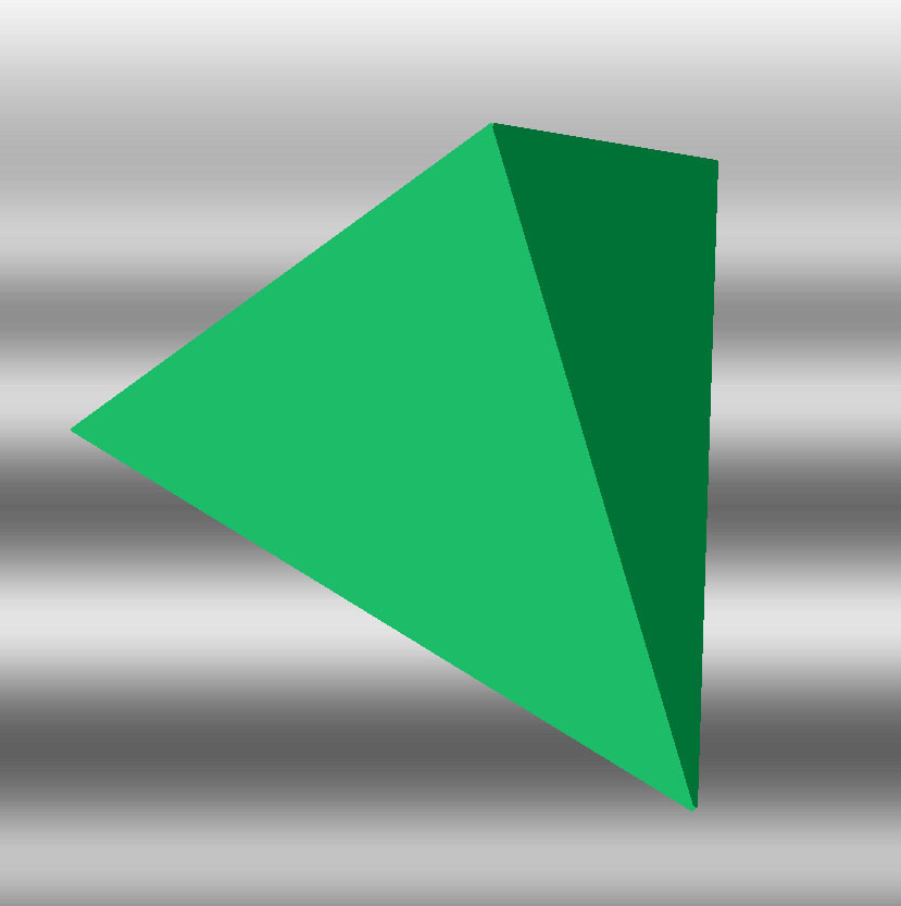
The simplest geometric shape that is used to create 3D computer models of solids is the tetrahedron (left). It has four triangle sides joining at four corners. The platonic (perfect) solid tetrahedron has four equilateral triangles for sides.
To make the growing structure twist, taper, and branch, however, the tetrahedral “cell” (which has no scientific relations to a real living cell) needed to be variably irregular, and not perfect. In an irregular tetrahedra the four triangular sides still join at four corners but are not identical equilateral triangles; they deviate from each other a bit in shape and size.
Growth (Growth Mechanism)
The “growth mechanism” (image #1 at right) was developed as a simple, intuitive way to attach the tetrahedra to one another. By connecting a new tetrahedral growth cell to the previous cell on a shared, common triangle face, three corners of the previous cell match three corners of the growth cell. Three corners of the growth cell are known and only the coordinates of the fourth corner need to be assigned.
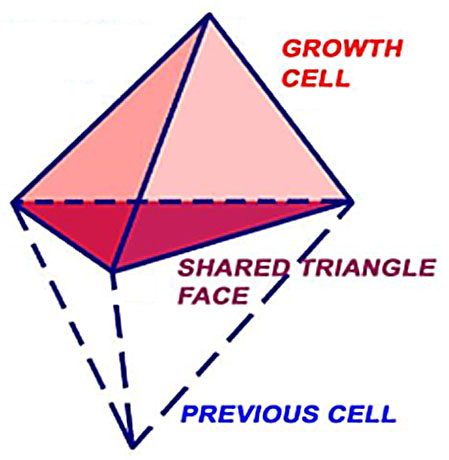
image by BGlover
The growth mechanism #2 image (below) shows five cells joined together – black, red, blue, green, and pink. The shared triangle face between each pair is shaded.
Look at the shared face between the green and pink tetrahedra. Here’s the rules that define the growth mechanism, based on labels at each corner on the image left:
- 3 corners of shared triangle face of previous green cell are A.4/B.4/C.4. (so for every cell = A.X/B.X/C.X)
- 3 corners of shared triangle face of growth pink cell are O.5/A.5/B.5. (so for every cell = O.X/A.X/B.X)
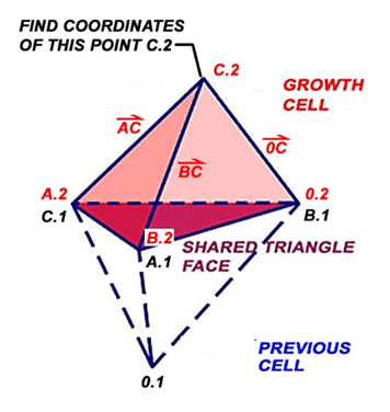
For each new cell “X” added, only the coordinates of point C.X of the growth cell need to be calculated to obtain the geometry of the growth cell.

image by BGlover
Genetics (Adaptive Code)
To obtain coordinates to point C.2 on the growth cell, vector mathematics and geometry are introduced to define an “adaptive code”, as shown in the growth cell geometry image (below). The adaptive code, which is a pattern programmed into a simple spreadsheet, determines coordinates of C.2 in the new growth cell.
After coordinates are established for the 3 corners of the shared face, the lengths of vectors AC, BC, and OC in the growth cell are assigned by the “code”.
Coordinates of point C.2 can be calculated, knowing that vectors AC, BC, and OC must intersect at C.2. This leads to a set of simultaneous equations, which when solved, results in C.2 coordinates. All coordinates for all 4 points of the growth cell – A.2, B.2, 0.2, and C.2 – are then known.
The growth cell then becomes the previous cell, and the next shared triangle face is determined. Then the growth pattern repeats.
Determining the Adaptive Code
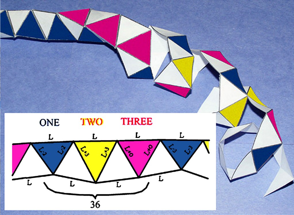
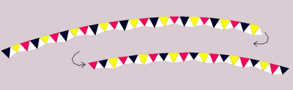
Influence of an adaptive code on a structure’s shape can be best described in a paper model image (below) of a structure’s construction as a folded paper 3D model. A paper strip is folded as shown into triangles, helically wound, then taped to the edge of the previous paper turn as shown.
Each third colored triangle with base length “L” has the same color, and each color forms one of three sides of a 3-sided helical structure. Colored triangles are isosceles, with lengths of two equal sides pre-determined in adaptive code programming. Irregular white triangles, between colored ones, have a length “L” between peaks of colored triangles so they can be taped to colored triangle’s base length “L” as the paper is wound helically.
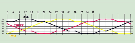
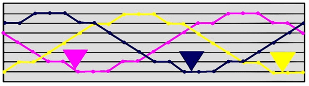
Below is plot image #0 of an adaptive code for a structure which will remain uniform in size yet uniformly twist. It plots the variation (dimensionless) in pre-determined length of two equal sides for each of the three colors of isosceles triangles. Although the wavelike plots of pre-determined lengths for all sets of colored triangles have the same shape as the others, they are out-of-phase with one another by an equal amount.
Below is the entire length of the strip of paper with colored triangles – paper strip image #0 (below). Its shape was computed from a spreadsheet, digitized and colored, then plotted on paper. This is the same strip folded and helically wound in the image above.
Example 1: No Twist or Taper
If all tetrahedra in a structure are regular, platonic tetrahedra with all triangular sides equilateral triangles, then there is no variation of triangle side lengths in the adaptive code plot image #1 (below).
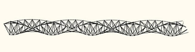
The resulting structure is uniform in size over its length and does not twist or taper – computer image #1 (below).
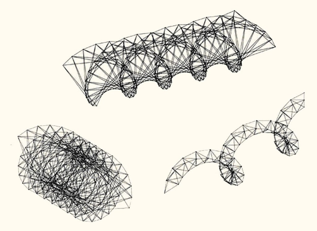
Example 2: Twist Only
As previously discussed, an adaptive code with out-of-phase, wave pattern functions for pre-determined lengths looks like the plot on the left, which is dimensionless – plot image #2 (below), which is similar to plot image #0.
Resulting 3D computer plots of structures with out-of-phase, wave patterns in their adaptive codes are shown below – computer images #2.
Differences between shapes in structures shown are made by adjusting the “wavelength” and “wave height” in the adaptive code functions.
The “wavelength” of the pattern is the rate of change in the size of triangles and the “wave height” is the magnitude of change in the sizes of triangles. With changing wave patterns, structures can twist tightly or can be quite open.
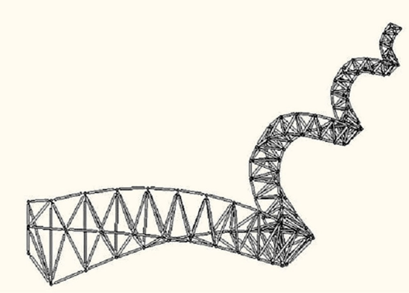
Example 3: Twist and Taper
Tapering width of a structure is done by superimposing a gradual, yet uniform, decrease in size of all cells on the adaptive code. Both base length “L” and pre-determined lengths of all colored triangles in the adaptive code are gradually decreased. In the adaptive plot image #3 (below), tapering is superimposed on out-of-phase wave functions for the pre-determined lengths.

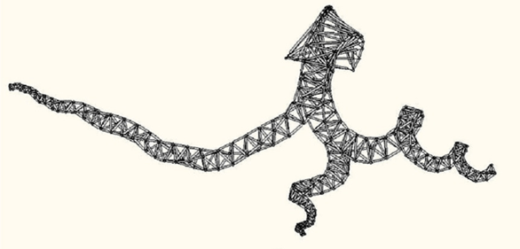
Example 4: Branching
Branching of a tapered, twisting structure is shown in the 3D computer image #4 below. Branches have different amounts of twist and taper.
Branching is done by using two of the triangular faces on a previous cell as two shared faces to attach two new growth cells to the single previous cell.

Leave a comment