Available Structural Units
War refugees and natural disaster victims must scavenge materials for their makeshift shelters, like those in Figure 1 from Haiti. What will their shelters look like? Well, it totally depends on what materials are scavenged and gathered, then carted away to the shelter site. If lucky, refugees get materials donated by relief agencies; materials from dumps are often added to this. Surveying the image below, one notices locally foraged materials – cardboard, metal siding, blue tarps, blankets, shipping pallets, and other discarded or donated materials. Available materials become their shelters.

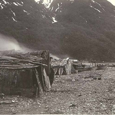
Fortunately, many of us have not lived long in temporary shelters. Our experiences are limited to assembling temporary driftwood “shelters” on beaches or pitching a tent or tarp for shelter while camping in the forest (Image 2). Packing in our own available materials for shelter makes sense in this “leave no trace” era. In contrast, Native Alaskans in SE Alaska built temporary seal hunting camps with shelters of driftwood picked from the beach (Image 3) and used them year after year if they withstood the storms.

Units All around Us
Stacked rocks we encounter while hiking indicates some beachcomber or hiker has stopped and spent time to find available rocks to stack (Image 4). Sometimes I wonder why we love to stack rocks. Yet, I stop and add a few rocks myself. Maybe it’s the thrill of stacking, aligning, and connecting we acquired as toddlers. We’d stack blocks high, and then we knocked them down, laughing and yelling, “Again, again…” We played with our children and grandchildren and their toys, especially made for stacking, aligning, and connecting (Image 4).


Single Units in Structures
Structures in the built environment are often constructed one unit at a time. Units are stacked, connected, and aligned to make a whole structure. Most structures are built from a variety of different materials, designed to work together. However, this article describes special single unit structures built entirely from only one type of unit. All construction units in the completed special single unit structures are similar in material, size, shape, and weight, and sometimes the units are identical, like wooden toy blocks.
Building a structure takes a lot of material. It is logical, then, that structures historically built with large quantities of readily available, locally found, single units became common. Easily recognized examples of historic single unit structures are: 1) log homes – with naturally occurring logs as units, 2) igloos – with locally packed snow bricks as units, and 3) brick buildings – with locally manufactured masonry units.
Below are a few examples of single unit structures constructed of various materials, demonstrating why single unit construction made sense for them.
Mortarless, Stacked Rock
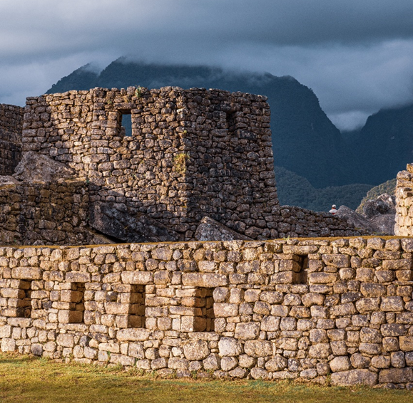
Andean Inca archeological sites contain examples of single unit structural walls made from available small rocks, stacked in mortarless arrangements, such as those in Image 5 at Machu Pichu. Roof structures were probably made of timber supported on the stacked rock walls.
Builders used relatively small and lightweight rocks for these structures’ walls, which could be scavenged locally in the area and manually hauled to the site. For small rocks, builders only needed manual labor and simple machines, tools, and scaffolding for construction. Other Machu Pichu structures used huge rocks requiring other means of construction. Small rocks were stacked into thick, tall walls with narrow windows and doors spanned overhead by stone lintels. Due to the walls’ thickness and variable angularity of rock units, they needed no mortar. Builders minimally shaped or carved rocks before placing them into positions for a tight fit. Smaller stones were inserted between units to further tighten the fit. Builders placed larger rock units at corners and ends of walls to strengthen these locations.
Another example of a single unit structure built with uncut, mortarless rock is from Ireland (Image 6). Truly a single unit structure, there is no timber or other material for the roof, which is a stacked rock dome. Builders used similarly shaped, flat rocks for their structure. Rock was scavenged locally; the flattest rocks were chosen for use. These flat rocks yielded tighter, more uniform bearing between rock layers, increasing stability and creating more uniform stresses. Builders utilized a unique structural system – walls and roof arching from ground to dome peak as one continuous structural element. Very clever, since gravity from arching compresses layers together, adding stability.
Where similar buildings of stacked, mortarless, unreinforced rock masonry were built in earthquake-prone areas of the world, few examples of similar stacked structures exist unscathed. No matter how tightly fit or thickly built the walls, these heavy buildings became susceptible to damage during earthquakes.

Cut Stone Monument
Great structures and monuments in the pre-Roman and Roman world were constructed using massive stone units – Stonehenge, Egyptian pyramids, Greek temples, and monumental Roman structures. The cost of human labor was expensive, and only made possible by using skilled slave labor. Construction projects lasted years, decades, or centuries. These stone structures reflect the monumental effort invested in their construction through their survival to the present. Due to their materials and construction, they have resisted dismantling, destruction, fire, and decay. Earthquakes and war, however, have damaged some of them.
Prior to cathedral-building centuries of medieval Europe, one must go back to the stone monumental structures built by Rome and Greece to find comparative structures. One such example, shown in Image 7, the National Archaeological Museum of Paestum in Salerno, Italy, is an ancient Greek structure which shows massive stone structural elements with visible joints between units. The timber roof structure was destroyed.
Greeks (and Romans) had machines to lift and place heavy stone units, but machines had lift weight limits. Stone units were undoubtedly sized and cut to fit within machine lifting capacities. Stone sizes and weight limits must have influenced the architecture and layout geometry – column spacing and number of columns, and probably a structure’s height and width as well.

There are 3 separate elements made from large cut stone single units needed to build the perimeter façade structure in Image 7, which will be focused on.
- Stones steps at grade
- Stone columns
- Stone lintels
Individual stone units of each element had small variations among them. For example, a corner lintel piece differs from a typical lintel piece in dimensions and cuts to make corners fit together. And some units were mirror image pieces from similar stone units.
Therefore, each element – steps, columns, and lintels – required several distinct, yet similar, sets of plans and details (templates) for producing each of the similar stone units. A template for each variation in an element’s stone units described or sketched in detail how the stone unit variation was cut, carved, transported, lifted, and set in place.
I’d guess 80% of the units for the large, cut perimeter stone steps at grade needed only 8 to 10 distinct step templates.
32 identical stone columns surround the perimeter above the steps. Each column is a stack of carved stone column section units. Since section units are identical in all 32 columns, each column template was used for at least 32 identical stone units. Assuming 12 stacked column section units, there are 12 sets of column templates for the entire structure.
A carved stone lintel of 34 identical (or similar) heavy, cut stone units rests atop perimeter columns. I’d guess these numbers of templates, including mirror image sets: a) 1 for 20 typical, side lintel sections, b) 2 for 4 end-piece, side lintel sections, c) 1 for 3 typical, end lintel sections, and d) 2 for 4 end-piece, end lintel sections.
The structure is symmetrical about both axes and repetitive in design. The total number of sets of plans and details for stone units in the façade is therefore rather small for a structure of this complexity and weight. Fewer number of templates simplifies the structure for construction.
Cut Stone Aqueduct
Another example, shown in image 8, shows the Roman aqueduct of Segovia, a massive cut stone Roman structure. How was this stone aqueduct structure conceived and built? Analysis of the structure is simpler since stone units are clearly visible, and joints between columns, arches, and aqueduct trough are distinguishable.

The aqueduct was linear, and if of sufficient length, was built linearly instead of vertical like a building, as long as stone delivery to all points along its length was possible. Long linear structures are usually built by staggering construction as construction progresses from start to end, as shown in Image 9 with teams of skilled builders, each assigned to an element of the structure, starting at staggered times. For much of the time, all elements are simultaneously being built.
- First to start their work were earthworks builders, who leveled and compacted soil below foundations, starting at one aqueduct end.
- Next, foundation builders started, moving from one column location to the next, building similar foundation units at each column over soil prepared by earthworks builders.
- Sometime later, lower column builders followed foundation builders along the aqueduct’s course. The column building “learning curve” reached maximum efficiency quickly due to repetition of column units, which only differ in length of bottom parts of columns.
- With lower columns built, lower arch builders began, following closely behind column builders. Forms for archway stones were re-used, moved from location to location.
- After lower arches were built, upper column builders started at the aqueduct’s beginning, followed by upper arch builders. Upper arch construction utilized the same formwork as the lower arches.
- Finally, the aqueduct trough builders started their work once some upper arches were finished. All aqueduct elements – foundations, lower columns, lower arches, upper columns, upper arches, and aqueduct trough were being constructed simultaneously, but in staggered locations along the aqueduct route as shown in Image 9.
Staggering construction of elements maximized the number of skilled workers working at one time on the aqueduct, as long as each individual element is assigned to one team of masons. The Romans recognized that staggering construction also maximized the number of workers on the job at one time. It was less efficient to finish all foundations first before starting columns or finish all columns before beginning arch construction.
NOTE: This theoretical sequence is understandably simplified and is heavily influenced by my experience with modern construction planning techniques. Vitruvius’ writings help us understand a little about Roman construction, but Romans with teams of slaves used many well-worn techniques we cannot imitate. As far as I know, no one has built an aqueduct using single stone units of this magnitude after the Romans.

If construction was staggered, each element – foundation, column, arch, and aqueduct trough – utilized a small team consisting of master masons plus assistants (slaves or unskilled workers) assigned only to that one element. The element’s team worked through a “learning curve”, learning skills and techniques taught by experienced masons before adequate quality and efficiency was reached by the whole team on the element. Construction of an element soon became routine.
Similarly, Romans achieved better quality and efficiency through repetition in their designs, in ways similar to how repetition was used at Paestum in Salerno. Notice how the same column and arch designs occur repeatedly in the aqueduct, leading to routine in construction.
Single stone units minimized number of template variations for stone fabrication and erection. Each team of masons was responsible for only a select few units and their corresponding construction. After a while, each team became experts in choosing stones of appropriate size and shape that minimized their work, well before the stones were placed. Work became repetitive, routine, efficient.
Brick
Roman bricks were the mainstay of the Roman construction industry. Inexpensive Roman bricks were mass-produced and used extensively to build new cities in the Empire. Roman legions carried mobile brick kilns with them, and clay was available near most sites. Lightweight bricks, small single units, were easy to transport and lift with locally available carts and manual labor. Brickmaking and brick-laying technology, brought by Romans to all regions of the Empire, was taught locally, introducing mass-produced, single unit brick technology for structures that would be used around the Mediterranean and in Europe for centuries to come.
Brick use in the Roman Empire is further discussed in my blog entitled “NATURALL CUBIC” https://numnum.blog/2023-03-04-naturally-cubic/
Wood
Wood implies warmth and life much more so than rock or stone or brick, since it comes from trees that once lived. It is a material still highly regarded for building dwellings and objects around us. Small villages in southern Poland and western Ukraine have some fences built with available wood sticks gathered from surrounding forests (two examples in Image 10). One senses each fence-builder’s individual pride in their woodcraft skills in these unique fences. Sticks – single construction units of varying size and shape – are arranged in personally creative, whimsical fence designs, creating a folk-art style unique to the region. Of special interest are fences with sticks woven in repetitive, geometrical patterns – reminiscent of braided hair or wheat stalks – between equally spaced vertical posts. Wood connections are key to successful wood construction, so it’s amazing no visible nails or other connectors are used to connect sticks together. Only weaving of the sticks kept fences in place.


In small, old Rusyn-Carpathian villages are many old, but sturdy, well-preserved homes built of logs cut a couple centuries ago. Traditional log houses have 3 connected compartments – living quarters at one end, barn at the other, and a threshing/storage area in the middle. Similarly sized logs, cut square into large timbers, are stacked and caulked to make thick walls. Prepping and placing logs are heavy tasks but require few extensive woodworking skills. Many traditional log houses are still occupied, with roofing materials upgraded from thatch to metal.
Image 11 (below) is an old 3-part house re-built in a folk museum in southern Poland. It is built with simple, traditional materials freely gathered locally – logs, hay (straw), sticks, and rocks. Image 12 (below) shows an occupied farmhouse in a small Carpathian village.


Log cabins are an historical image from America’s history. Log cabins are not an American invention, though, as immigrants brought an old technology to North America where timber was plentiful. Settlers cut logs from trees near homesites throughout North America, wherever single log construction units were readily available and “free to use”.
One basic connection type is typically seen between logs in Europe and America – the interlocked corner joint (Image 13 from Alaska). Each log end is notched to fit as snugly as possible in a notch cut in the log end below it. Sounds easy, but it’s not, as evidenced by rough variations shown in Image 13. Not all logs are trimmed square, but it is more common in colder climates.
Timber construction units come from living plants, which gives log home building some unique construction issues. Although treated like single units, they are hardly identical unless manufactured to be so. Trees taper in diameter, and so do logs cut from them. Trees vary considerably in diameter and are often not straight. And, remember that wood shrinks as it dries out.
The better log homes were built centuries ago by builders with experience and knowledge in detailing around properties of trees and logs. Logs were laid out to dry before starting construction, although the wood would continue to dry after construction. Horizontal joints between square-trimmed logs of homes in eastern Europe were quite narrow, displaying evidence of fitting a log layer to logs below it. Corner joints were notched tightly, leaving greater log end lengths past the notch. Caulking in these older log homes was often grout or plaster-based, often repaired as logs swell and shrink.
Now, manufacturers and builders of log homes prepare logs and build with them to make modern, comfortable homes.
A Unique Log Structure
Being a Pacific Northwest native, I grew up in areas with logging. Often, when hiking, we’d see a few old steel rails and wire ropes from old logging operations. But when seeing this old photo – a rustic log “bridge” structure in Image 14 – I was fascinated and wondered why the bridge was built this way. The structure is of single units – logs – stacked to make a logging railway bridge over a ravine.

Other options for spanning the ravine were to 1) use earthen fill with a large culvert for the ravine bottom’s creek, or 2) haul in a steel bridge, or 3) build a permanent log bridge, perhaps publicly accessible. All these options might have had public accessibility issues with the bridge.
The bridge’s log units as shown had several advantages over bridge options above. First, logs were readily available (and free for use) to the loggers, but a steel bridge was costly to procure, transport, and erect. Second, issues with moving wet soil and moving heavy machinery along muddy creek banks created big, messy, expensive problems. Third, if someone else besides the loggers designed, procured, and paid for a permanent log bridge then the loggers would be no longer fully be in charge of their own operation.
At first glance, one might think this is a total waste of timber. But think instead of how these loggers ”stored” these logs temporarily in a well-ordered pile on their way into the forest, creatively using a log storage pile as a bridge along their route into the forest. Stored logs in the bridge were later collected as loggers left the forest. Since the temporary bridge was used only by the logging company – and not the public – loggers had exclusive rights to the bridge and were responsible for it only to themselves.
After completing the railroad track line to its end, including the bridge, all timber along the rail route was harvested. After harvesting, the railroad and its bridges were de-constructed starting at the end of the rail line deep in the forest. As tracks were removed, train engines and railcars would still be able to travel on remaining track out of the forest, hauling decommissioned steel rails and ties out. After crossing the bridge on the final trip out of the forest, the bridge’s logs were lifted and placed on railcars for transport out. All logs were harvested and cut for lumber.
A possible sequence of construction of a log bridge over a ravine is shown in Image 15 and described below, demonstrating advantages to the logging company in having readily available single log units for construction.
- Logging railway stops at top of ravine.
- A log bridge on piles, perpendicular to creek, is installed. Logs parallel to creek are then lifted by railway crane down onto bank and placed atop log bridge.
- First layer of logs parallel creek completed.
- Second layer of logs perpendicular and parallel creek is installed.
- Subsequent layers of logs are installed.
- Top of ravine is reached. A flat wooden bed for railroad tracks is laid.
- Wood ties and steel rails are laid across bridge atop flat wooden bed.
- The bridge is tested with weight of train engine and loaded railcars.


Note: All sequences of construction in this article are based on my own assumptions based on personal experience.
Further Articles on Single Unit Structures
2023 APRIL 29 GALLERY OF SINGLE UNIT STRUCTURES The use of single unit structures in engineering and architecture is highlighted in this Photo Gallery. numnum.blog/gallery-of-single-unit-structures/
2023 APRIL 29 PLAYING WITH SINGLE UNIT STRUCTURES Can you invent a hypothetical single unit structure? Sketches and models from several of my studies are shown which use identical single units. numnum.blog/playing-with-single-unit-structures/

Leave a comment